
Existing cabling may be reusable, but a clear label alone cannot show whether a link works properly. A patch panel port labelling and tracing service in Dubai can map each connection and test existing runs before you decide whether replacement is needed. Keep cabling that passes the relevant tests, and replace runs that fail or need different cable to support faster speeds.
It’s reasonable to want a tidy rack without replacing sound cabling or unnecessarily disrupting a working network. Reliable records start with tracing each link, recording tester results against its identifier, and matching panel ports to switch ports and desks.
This guide explains how to use tester data, build a useful port map, and apply consistent names across labels and records. It also introduces ANSI/TIA-606-D, a standard for telecommunications infrastructure administration, and shows how an organised relabelling process can make future troubleshooting and upgrades more straightforward.
Key Takeaways
- Keep tester results tied to each link’s identifier, test configuration, selected limit, and outcome so they’re useful for upgrade decisions.
- Build a port map that connects each patch-panel port to its switch port and destination desk.
- Use a consistent code at both ends of each cable to make tracing and troubleshooting more straightforward.
- Choose front and rear panel identifiers that stay readable and match the records technicians use.
- Use ANSI/TIA-606-D as a framework for consistent infrastructure labels and administration records.
Tracing links with Fluke and AEM tester data
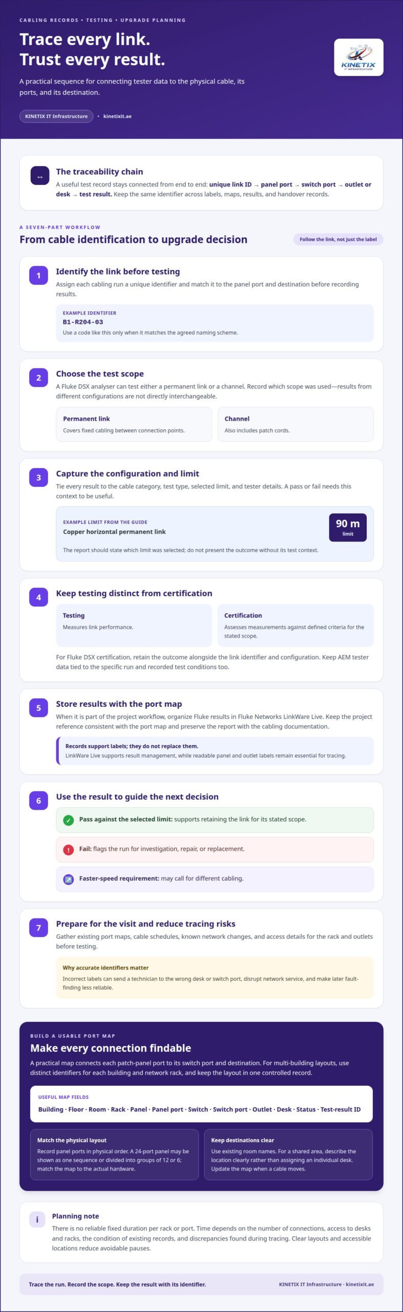
When comparing providers in Dubai, ask what test equipment they use and what records they deliver. A useful report ties each result to a link identifier, test configuration, selected limit, and outcome.
- Define each link before testing. Assign a unique identifier to the cabling run, then match it to the panel port and destination. For example, record a run as “B1-R204-03” only if that code matches the agreed naming scheme. This prevents results from becoming detached from the physical cable.
- Choose the correct test scope. A Fluke DSX analyser can test a channel or permanent link. A permanent-link test covers fixed cabling between connection points; a channel test also includes patch cords. Record the scope used, because results from different configurations are not directly interchangeable.
- Set the test configuration and limit. Capture the cable category, test type, selected limit, and tester details with every result. For example, a copper horizontal permanent link has a 90-metre limit. The report should make clear which limit was selected, rather than presenting a pass or fail without context.
- Separate testing from certification. Testing measures link performance; certification assesses those measurements against defined criteria for the stated scope. With Fluke DSX certification, retain the outcome alongside the configuration and link identifier. AEM tester data should also remain tied to the specific run and its recorded test conditions.
- Keep the data traceable. Organize Fluke results in Fluke Networks LinkWare Live when it is part of the project workflow. Keep the project reference consistent with the port map, and preserve the test report with the cabling documentation. LinkWare Live supports result management; it does not replace clear labels at the panel and outlet.
- Use the results to guide upgrades. Review each tested run before deciding whether it can remain in service. A passing result against the selected limit supports retaining the link for its stated scope. A failed result flags a run for investigation, repair, or replacement, while a faster-speed requirement may call for different cabling.
- Prepare for the visit and reduce tracing risks. Before testing, gather existing port maps, cable schedules, known network changes, and access details for the rack and outlets. Incorrect labels can lead a technician to the wrong desk or switch port, disrupt network service, and make later fault-finding less reliable. Accurate records help prevent these errors.
Creating a port map for panel ports, switch ports and desks
A useful port map connects each patch-panel port to its switch port and destination desk. For structured cabling across multiple buildings, keep the layout in one controlled record, with distinct identifiers for each building and network rack. The steps below show how to make the map practical to use.
- Set the map’s location structure. Start with building, floor, room, and rack fields. Then assign each panel and port a unique place in that hierarchy. For example, a Building 1 rack should not share its panel identifier with a rack elsewhere. This makes records easier to follow when layouts span several buildings.
- Record the panel ports in physical order. Enter each port as it appears on the panel, including its panel identifier and position. A 24-port panel can be represented as one sequence or divided into groups of 12 or 6. Match the map’s arrangement to the actual hardware, so a technician can find the listed port without translating between formats.
- Add the switch destination. Create a separate field for the switch identifier and switch port. Record the precise connection, such as “Panel A, port 01 → Switch A, port 01.” Keep panel and switch identifiers distinct; similar-looking port numbers alone can lead to confusion during changes.
- Describe the outlet and desk. Add the room and desk destination for each run, using the building’s existing room names. If a port serves a shared area, describe that location clearly rather than assigning an individual desk. This gives support teams a destination they can recognize without relying on memory.
- Keep the columns consistent. Include fields for building, room, rack, panel, panel port, switch, switch port, outlet, desk, and status. Avoid combining several details in one notes cell. A consistent layout lets technicians sort by room or switch and find a connection without scanning unrelated entries.
- Connect records with test results. Match each mapped run to its corresponding test-result identifier and current status. When a cable is moved, update the panel-to-switch relationship and destination together. This keeps the documentation aligned with the installed network rather than preserving an obsolete connection.
- Plan the work around its complexity. There is no reliable fixed duration per rack or port. Time depends on the number of connections, access to desks and racks, the condition of existing records, and discrepancies found during tracing. A clear layout and accessible locations reduce avoidable pauses.
For a physical cabling layout that needs organised connections and records, network cabling support can be a natural next step.
Consistent naming conventions
A naming format turns labels into usable records rather than isolated codes. For each connection, keep the identifier consistent across cables, outlet labels, panel records, test results, and handover documentation. Use the following steps to create a scheme technicians can read and maintain.
- Choose a location-first structure. Start with a building or site code, then add room and outlet details. For example, “B1-R204-03” can represent Building 1, Room 204, outlet 03. This format helps distinguish similar connections in separate rooms or buildings without relying on handwritten descriptions.
- Define each code element. Write down what “B1,” “R204,” and “03” mean before applying labels. Keep the same order on every record. If a building uses a different room format, document that difference rather than silently changing the code midway through the installation.
- Keep identifiers unique. Each outlet and cable connection needs a code that points to one location. Avoid reusing “03” across records without its building and room elements. A complete identifier such as “B1-R204-03” gives technicians more context than a number that only makes sense beside one panel.
- Apply one format at both cable ends. Put the same identifier at the outlet end and rack end of each cable. If a connection has a separate panel-port reference, record it as a related field rather than changing the outlet code. This keeps the cable identity stable when its switch assignment changes.
- Use readable separators and characters. Choose a simple format that distinguishes letters from numbers, such as “B1-R204-03.” Avoid inconsistent spacing, unclear abbreviations, or variations like “B1 R204 3” for the same connection. A uniform code is easier to search in a spreadsheet and compare during testing.
- Match labels to records. Update the written schedule whenever a cable, outlet, or connection changes. Remove the previous assignment from active records or clearly mark it as retired. During testing, link results to the current identifier so a pass or failure cannot be mistaken for another cable’s result.
- Make the scheme part of handover. Include a short legend, the naming format, and a sample code in the final documentation. For example, explain that “B1-R204-03” identifies an outlet, while its panel and switch references appear in separate fields. This gives future technicians a clear starting point.
Front and rear panel identifiers
- Assign each panel a stable identifier. Give every patch panel a unique name within its rack, such as “R01-PP01.” Keep that identifier in installation records and the port map. The front label should identify the panel, while each port label identifies its position. This distinction helps technicians avoid confusing a panel reference with a copper cable or outlet code.
- Make the front readable at the rack. Place port numbers where they remain visible beside the corresponding sockets. Use a clear sequence that follows the panel’s physical layout, then check that labels do not cover ports or obstruct patch leads. A technician should be able to match a visible number to its record without pulling connected cables from the cabinet.
- Use compatible inserts where available. Some patch panels have a clear plastic window with a slot behind it. For these models, use non-adhesive inserts sized to fit the slot. A fitted insert can be replaced without putting a new sticker over the panel face. Check the panel’s design before preparing inserts, since layouts differ.
- Label the rear terminations as well. At the back of the panel, match each cable identifier to its front port position. Rear labels should remain legible after the bundle is dressed and secured. Leave enough clearance to read the code without disturbing adjacent terminations. This makes tracing possible from either side during installation or later fault-finding.
- Identify both ends of every cable. Print a smudge-proof label for each end, using the same cable code at the panel and outlet. Position each label so it can be read without bending or disconnecting the cable. For example, a technician tracing a run from a cabinet can compare its identifier directly with the outlet record.
- Keep cable and port references distinct. A cable code describes the run; a panel-and-port code describes its termination. Record the relationship between them rather than treating them as interchangeable. If a copper run moves to another panel port, update that connection in the records while preserving the cable’s identifier and outlet destination.
- Review labels after changes. After installation or a rearrangement, check front identifiers, rear terminations, and outlet labels against the current schedule. Replace labels that are obscured, damaged, or inconsistent. A final visual review catches mismatches before the cabinet is closed and keeps the physical panel aligned with its documentation.
Naming schemes and ANSI/TIA-606-D
ANSI/TIA-606-D provides a framework for consistent telecommunications infrastructure identification and records. A naming scheme should make each identifier useful on labels, drawings, and maintenance documentation. Follow these steps to shape a scheme around the installation rather than a single panel.
- Choose the scope before creating identifiers. List the infrastructure elements that need names, such as buildings, rooms, racks, panels, ports, and outlets. For a single rack, a code like “R01 PP01 01” can identify rack 01, patch panel 01, port 01. Keep each code’s meaning in a short legend.
- Use an identifier format that fits the site. ANSI/TIA-606-D provides identifier-format families compatible with ANSI/TIA-606-A and ISO/IEC TR 14763-2-1. Select a format that suits the site’s structure and existing records. Keep its sequence consistent, so “R01 PP01 01” doesn’t appear elsewhere with a different meaning.
- Separate location from equipment identity. Record the building or room separately from a rack or panel identifier when the scheme requires both. This keeps a panel’s identity distinct from its location. For example, “Building 1, R01, PP01” conveys more context than “PP01” alone across several areas.
- Define the scheme’s boundaries. Record which identifiers apply to spaces, pathways, cabling, and equipment. ANSI/TIA-606-D defines four administration classes for telecommunications infrastructure. Use the class suited to the scope being administered, then keep records aligned with that scope instead of mixing site-wide and room-level identifiers.
- Keep existing references clear during upgrades. ANSI/TIA-606-D replaced ANSI/TIA-606-C, which dated from June 2017. For an existing installation, document the identifiers already in use before changing them. Map old references to new ones in the project records, so technicians can follow connections during the transition.
- Apply the format across labels and records. Use the same identifier in the schedule, panel documentation, and relevant cable records. If “R01 PP01 01” names a panel port, preserve that exact sequence wherever the port appears. Consistency lets a technician move from a physical label to its corresponding record without translating codes.
- Make the naming scheme part of handover. Include a legend, scope, and sample identifiers in the final documentation. Note how additions should be named, so later cabling installation work follows the same pattern. Organise your cabling records around a clear, consistent scheme.
KINETIX IT Infrastructure
KINETIX IT Infrastructure helps connect clear network records with a more reliable home or office network in Dubai. When tracing shows that coverage, rather than a cabling fault, is the remaining concern, Wi-Fi Troubleshooting & Repair can help identify the issue. For weak-signal areas, Wi-Fi Dead Zone Fixing and Wi-Fi Optimization address coverage and performance needs, while Wi-Fi Installation & Setup supports a new or updated setup.
Share the affected areas, the devices that rely on the connection, and any relevant network map or test records. This context helps align the next step with the problem you are trying to solve, without treating every network issue as a need to replace cabling.
Contact KINETIX IT Infrastructure to discuss your network needs.
Keep network changes easy to manage
A useful next step is to assign responsibility for updating network records whenever a connection changes. Without that habit, even a carefully organized map can drift from the live setup. Make record updates part of the change process so future troubleshooting starts with dependable information instead of guesswork.
If you’re planning patch panel port labelling and tracing in Dubai, consider how the wider network will support your next move. KINETIX IT Infrastructure can help with related needs such as Wi-Fi Installation & Setup, Wi-Fi Troubleshooting & Repair, and Wi-Fi Dead Zone Fixing. Choose the support that fits the issue, whether you’re addressing coverage or resolving a connection problem.
Contact KINETIX IT Infrastructure to discuss your network needs and take a clear next step.
Frequently Asked Questions
Can you upgrade or relabel my existing cabling?
Yes. Existing cabling can be traced and relabelled, with replacement decisions based on test results and the network’s speed requirements. For example, a run that passes the relevant test may remain in use, while a failed link can be investigated for repair or replacement. KINETIX IT Infrastructure provides Network Cabling for home and office network projects.
What documentation and test results will I receive?
A useful handover includes a port map, label schedule, and test report linked to each cable identifier. The report should show the test configuration, selected limit, and outcome, giving each result clear context. Records should also capture the panel, switch, and outlet relationships. For example, if a desk connection moves to a different switch port, the updated schedule should reflect the change.
What does patch panel port labelling and tracing service in Dubai include?
The work can include identifying cable paths, matching panel ports with their destinations, applying consistent labels, and recording connections in a port map. Testing can help distinguish a working link from one that needs investigation. The scope depends on the project’s needs, such as relabelling existing runs, updating records after network changes, or assessing cabling before an upgrade. KINETIX IT Infrastructure provides Network Cabling for network projects.
How do Dubai technicians trace network ports from patch panels to wall outlets?
Technicians start with the rack and existing records, then identify a panel port and trace its corresponding run to the outlet. They record the panel, switch, and destination relationship under a consistent identifier. Tester data can then be associated with that link. If the outlet does not match the schedule, the map is corrected so future support teams can work from the current connection.
What standards and labeling conventions are used for patch panels in UAE offices?
ANSI/TIA-606-D is a telecommunications infrastructure administration standard used as a reference for consistent identifiers and records. A practical scheme assigns distinct codes to locations, racks, panels, and ports, then uses those codes consistently in labels and documentation. For example, “R01 PP01 01” can identify a rack, patch panel, and port. The code legend should explain each part clearly.
What equipment is used to trace and certify network ports?
A Fluke DSX analyser can test a channel or permanent link, and AEM tester data can also be associated with individual cabling runs. Certification assesses test measurements against the selected criteria and scope. Fluke Networks LinkWare Live can help manage Fluke results as part of a project workflow. The report should connect equipment data to the link identifier and its test configuration.
What information should be recorded in a patch panel port map and label schedule?
Record the building or site, room, rack, panel, panel port, switch, switch port, and outlet or desk destination. Include each run’s identifier and status, then connect the relevant test result to that entry. A sample record might show “R01 PP01 01” linked to its switch port and room outlet. Add a legend defining abbreviations so another technician can interpret the schedule.
Do Dubai data cabling providers offer after-hours patch panel tracing and labeling?
Rack tidy-ups can be scheduled early in the morning or after closing to reduce disruption. Check building rules and arrange contractor approval or after-hours access before the visit when required.